Hints & Tips - Common Practice Issues in the Plan Creator
1 Use a pdf print for a quick final check
Remember, before you complete your DCU/COF it is best practice to generate a PDF print of the title in Plan Creator to ensure that all references are displayed correctly. This is done by using the Save & Print function in the Toolbar.
- it is a quick way of checking that all references are displaying in the correct order, with nothing being obscured by another reference (see below for Section 5 - Get the Order Right for more tips on ordering of references)
- it is a quick way of checking that you haven't accidentally pasted in an additional polygon, line or point from the index layer that is not needed for the mapping of your title.
2 Ensure that polygons, lines and points are classified correctly
The classification of references is a new concept in the Plan Creator, and care should be taken to select the correct categorisation for each reference you are adding or updating. Full guidance on classifications can be found here - Using Classifications in the Plan Creator.
- the ownership of flats on floor levels should be classified as Ownership of Strata
- the ownership of common areas, even those on floor levels within tenements, should be classified as Ownership - Shared
- the tenement steading cadastral unit does not show ownership, instead it should be classified as Tenement Steading
3 Cut out a hole, don't use a white tint polygon
Previously in the DMS, if we needed to show that an area contained within a tint reference was not included, we had to draw a second polygon, tint it white & display it on top of the (pink) tint. This was because the DMS did not allow us to actually cut a hole out of a polygon. The Plan Creator does allow us to cut out the hole, or merge neighbouring polygons to wrap around the hole, meaning it's all related to the polygon data and there's no risk that the layers get accidentally muddled up with the white polygon hidden by the tint (a common problem in complex DMS titles).
Guidance on the use of the Cookie Cutter tool and the Split & Merge tools can be found here - Plan Creator Toolbar.
|
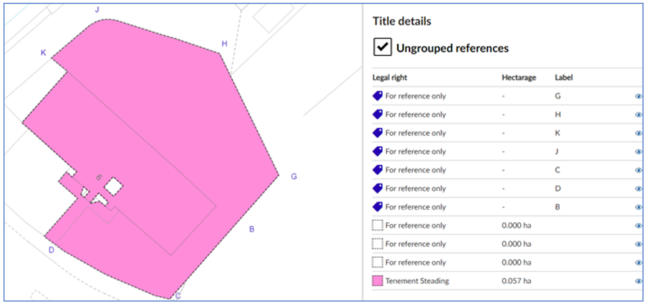
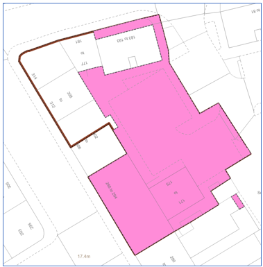
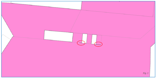
In this example of incorrect practice, the plans officer has not cut the three excepted areas or holes out of the Tenement Steading polygon using the Cookie Cutter tool. Instead they have created three additional polygons, tinted them white, stacked them on top, and classified them as For Reference Only. This is incorrect.
Correct practice is to use the Cookie Cutter tool to cut the three holes out of the pink polygon, or to build up the pink polygon around the three holes using the Merge tool to combine smaller polygons you have created. N.B. You may also notice that the boundary references have been labelled incorrectly too - see the section, below, for more help with Labelling in the Plan Creator |
4 Labelling is different now
Adding labels to references is done differently in the Plan Creator, and care should be taken to follow the new practices. Full guidance on classifications can be found here - Adding Labels in the Plan Creator.
In the DMS, labels, letters and numbers were added as free text references that were independent of the polygon, line or point they were labelling. There was no connection at database level between the mapped reference and the label. In the Plan Creator, labels are added as attributes to the polygon, line or point reference, and are therefore associated with that reference at database level.
- labels for boundaries are added via the Boundary Reference option in the Classification menu
- labels for polygons are added via the Add Label option in the Classification menu
- labels for lines/polylines are added via the Add Label option in the Classification menu
- labels for points are added using the Draw Point function in the Toolbar
|
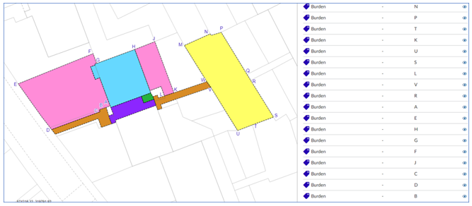
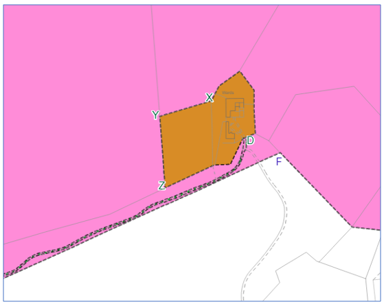
In this example of incorrect practice, the plans officer has not used the Boundary Reference option in the Categorisation menu to associate the boundary references with the various polygons. Instead, each individual letter has been added as a separate point reference and categorised as a burden. This is incorrect.
Correct practice is to use the Boundary Reference option when classifying each polygon that requires a boundary reference. N.B. You may also notice that the letter references haven't been dragged away from the points to create call-out/label lines therefore making it harder to visually identify which points the letters refer to. |
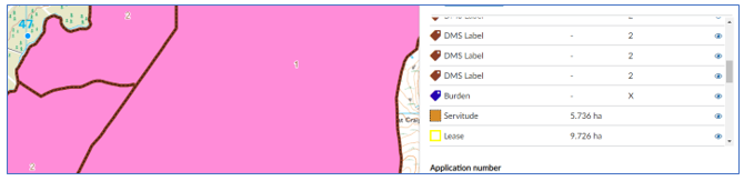 |
In this example of incorrect practice, the title was originally mapped in the DMS but has been incorrectly updated in the Plan Creator. When updating, the plans officer has not used the Add Label option in the Categorisation menu to replace the old numbers and associate new polygon labels with the brown edged polygons. Instead, the individual number references have been left as separate point references and haven't been categorised. This is incorrect.
Correct practice is to delete the old number reference and recreate a new polygon label using the Add Label option when classifying each polygon that requires a label. |
5 Get the order right
The layer order of polygons and other references is very important as you need to ensure that all references are visible on the cadastral map. There are now rules built into the Plan Creator for the render order of different types of plans reference - see Plan Creator Render Order Rules for full details.
It is, however, still possible to change the order of the tinted polygons that you have created to put them into a particular order for display. To do this, click and hold your mouse on the name of the reference or polygon that you would like to move, then drag the reference up or down the list until it is in the order you would like. A PDF print should still be generated in Plan Creator to ensure all plans references are clear and visible for the customer.
- edges should sit on top of tints
- hatches should sit on top of tints
- don't use multiple edges - consider the use of groupings if your title is particularly complex.
| 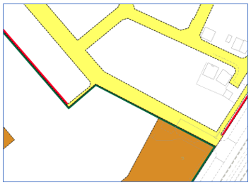 |
In this example of incorrect layer ordering, the pink tint is sitting on top of the brown edge and obscuring large parts of it. This has happened because the reference that has been tinted pink is higher up in the list of references than the brown edged reference. Whilst this would now be prevented by the Render rules built into the Plan Creator, the plans officer should have spotted this (perhaps when doing their quick final check using the print pdf check) and amended the order of the references in the list so the pink tint reference was listed beneath the brown edged reference. | In this example of incorrect layer ordering, the yellow tint is sitting on top of the red edge and obscuring parts of it. This has happened because the reference that has been tinted yellow is higher up in the list of references than the brown edged reference. Whilst this would now be prevented by the Render rules built into the Plan Creator, the plans officer should have spotted this (perhaps when doing their quick final check using the print pdf check) and amended the order of the references in the list so the yellow tint reference was listed beneath the red edged reference. You will note that the brown tint and green edge reference are in the correct order as the tint is not obscuring the edge. |
6 Don't use hatches and edges for small or narrow polygons
So that the full extent of all references are clearly visible on the cadastral map, do not use hatches or edges on very small or narrow polygons.
- edges can look like fills on small or narrow polygons
- hatches do not clearly show the extent of small areas where only a single hatch line may fit in the polygon
- hatches do not clearly show on narrow linear polygons (such as tracks) due to the spacing and orientation of the hatch lines
Alternative references should be used, perhaps by re-organising the references being used for the various polygons you are mapping, perhaps by using polygon labelling so the same reference can be used several times for different polygons, or perhaps by making use of the groupings function if your title is particularly complex. Before using the groupings function in such a scenario, you should discuss the options available with your referral officer.
|
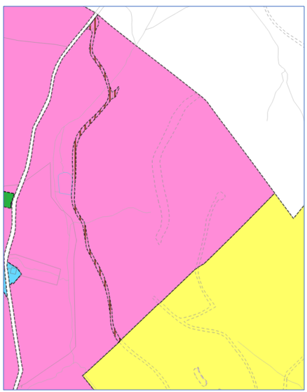
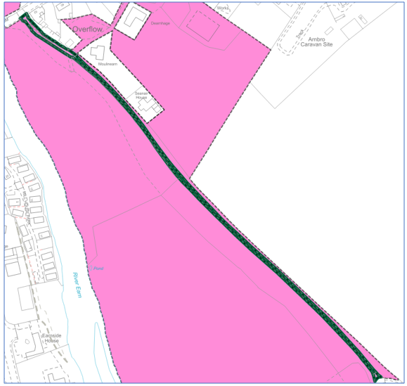
In these example of incorrect practice, the plans officer has used a hatch to reference tracks. This is incorrect. The hatch does not clearly identify the extent of the polygon, in particular in the first example, you can see that hatches do not work well on roughly vertical linear polygons. Correct practice here would be to re-organise the references being used and provide a tint for the track, perhaps making use of a grouping for an additional view or layer of the cadastral map if the title is particularly complex. N.B. You may also notice that the letter references on the second example haven't been dragged away from the points to create call-out/label lines therefore making it harder to visually identify which points the letters refer to. |
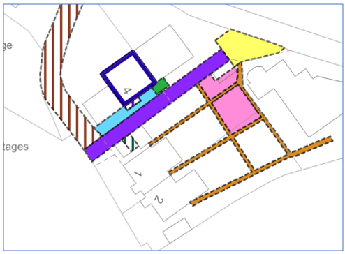 |
In these example of incorrect practice, the plans officer has used hatches to reference two very small areas - hatched blue and green. This is incorrect. The hatch does not clearly identify the extent of the polygons, in particular, the area hatched blue is so small it incudes only a single hatch line. Correct practice here would be to re-organise the references being used and use tints for the two areas, perhaps by using hatches for the areas currently tinted mauve and yellow, thus freeing up those two tints for use on the small areas. |
 |
In these example of incorrect practice, the plans officer has used an edge to reference a track. This is incorrect. The edge effectively fills the whole width of the polygon, making it difficult for the viewer to identify which area is edged and which is filled. Correct practice here would be to re-organise the references being used and provide a tint for the track, perhaps making use of a grouping for an additional view or layer of the cadastral map if the title is particularly complex. |
7 Watch out for slivers or bad geometry
Care should be taken when merging or splitting polygons (especially ones brought forward from the index layer that were originally created in the DMS) that no slivers or bad geometry are created in your title.
Example of typical "bad geometry"
|
|
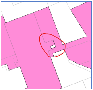
When the adjoining polygons were merged, leaving 3 intentional island sites or holes in the pink polygon, two of the holes contained slivers. These need to be removed. | |
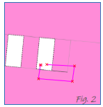
1. Select the Split tool and create a split which encompasses the sliver area. (Note that the classification is lost when the polygon is split). |
|
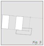
| 3. Delete the newly created polygon. | 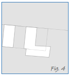 |
| 4. Use the Parallel Line tool to create a ray of the now partial side boundary of the polygon | 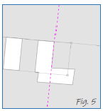 |
| 5. Use Autofill to fill the area now restricted by the construction line. | 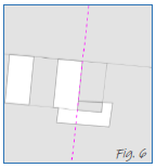 |
| 6. Delete the construction line. | 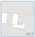 |
| 7. Use Autofill again to fill the other area. | 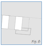 |
| 8. Select the polygons. | 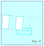 |
9. Merge the polygons - the sliver has now gone. (The merged polygon should now be re-classified). | 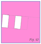 |
Please note, depending on your particular scenario, you may have to merge the polygons in a specific order, or only two at a time, in order to achieve the correct result. If you need to experiment to get the result you want, the Undo & Redo buttons may be helpful to you.
8 Be sensible with groupings
One of the new features of mapping in the Plan Creator is the use of groupings. This allows plans references to be placed on additional layers (or views) of the cadastral map, which at present take the form of additional plans or extracts from the cadastral map.
However, just because a plans reference could be put in a separate grouping or layer doesn't mean that it should be. Whilst the function allows for a lot of flexibility in the way titles are structured in the cadastral map, a consistent approach must be followed so that a consistent style of title sheet is produced. For details of the scenarios when it is appropriate to place references in a group, please see the Further Guidance page on Groupings.
9 Zoom level issue & how to resolve it
A known issue in the Plan Creator is that all the polygons seem to be sitting slightly away from the OS detail, even though those polygons have been brought forward correctly from the Base Map.
| This issue is caused by the zoom level on the browser window not being set to 100%. Fixing this issue is straightforward. |
|
| Click on the ellipsis (three dots) at the top right hand side of the browser window. |  |
Reset the zoom level to 100%. After this amendment is made, the browser must be refreshed - this can be done by either closing all Chrome windows that are open, or by pressing the F5 button in the top row (Note, press the fn button + F5 button on a laptop). | 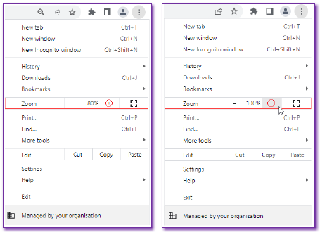 |
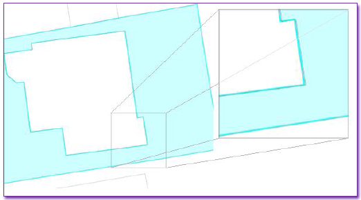
| The polygons should now be sitting correctly on the OS detail. | 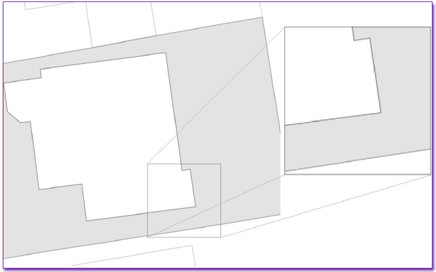 |
Registers of Scotland (RoS) seeks to ensure that the information published in the 2012 Act Registration Manual is up to date and accurate but it may be amended from time to time.
The Manual is an internal document intended for RoS staff only. The information in the Manual does not constitute legal or professional advice and RoS cannot accept any liability for actions arising from its use.
Using this website requires you to accept cookies. More information on cookies.
Feedback