Labelling in Plan Creator
- Editor9
Labels can be applied within Plan Creator in three separate ways (there is also a separate sub-section for the special situation we encounter with City of Edinburgh Council cases and their boundary references):
Labels should be positioned to enable the letter reference to be clearly seen on the cadastral map, and therefore should be positioned in blank space with no underlying detail, where possible. The length of the call-out lines to create the labels should be appropriate to the scale of the PDF print generated in Plan Creator, but as a guide, the lengths should be approximately as follows:
1:1250
- Draw point labels: Minimum length 8m up to a maximum in most cases of 15m
- Call-out labels: Minimum length 5m up to a maximum in most cases of 10m
1:2500
- Draw point labels: Minimum length 15m up to a maximum in most cases of 20m
- Call-out labels: Minimum length 10m up to a maximum in most cases of 20m
1:10000
- Draw point labels: Minimum length 70m up to a maximum in most cases of 100m
- Call-out labels: Minimum length 50m up to a maximum in most cases of 100m
Note that the minimum length of Draw point labels is longer than call-out labels because of the arrowhead generated. The length of the label can quickly be checked using the measure tool in Plan Creator if this is felt necessary, but the PDF should always be checked to ensure visibility of references for all cases.
1 - Add a Boundary Reference
1.1 Polygon boundary references
When the deed or deeds being examined as part of the registration process contain details of burdens, rights or even ownership pertaining to one or more boundaries of a plot of land being registered, then labels should be added to the affected parts of the polygon so these can be referred to by the legal settler in the title sheet. For example, the deed may specify that the wall on the northern boundary between two points shown on the deed plan is to be maintained solely at the expense of the owner of the plot, but that the fence on the western boundary between two points shown on the deed plan will be maintained jointly by the two owners of the land on either side. This is important burden information affecting the title and will therefore need to be included in the title sheet.
The labels are added using the Classification menu in Plan Creator, and details of the process can be found in the Plan Creator Technical Guide - 5.0 Classifications.
When adding a boundary reference label in this way, the boundary has to be classified. In most scenarios, it will be clear whether the reference is being added because it is a burden (e.g. obligation to maintain or pay costs) or because it is an ownership reference (e.g. exclusive ownership of a wall, or shared ownership of a fence, etc).
Occasionally, boundary reference labels will need to be added in relation to a natural water boundary (NWB). In this scenario, the classification of the boundary should follow the classification of the polygon. For example:
- polygon affected by NWB is classified as Ownership - Exclusive so boundary reference is classified as Ownership - Exclusive.
- polygon affected by NWB is classified as Lease so boundary reference is classified as Lease.
Description
For boundary labels assigned to polygons, the text colour (and any call-out line) will always be blue irrespective of the tint or edge colour applied to the polygon
Boundary labels that are assigned to polygons for ownership or burden reasons should be narrated in the title sheet as, for example, "the boundary labelled A to B", or "the boundary labelled R to S".
Examples
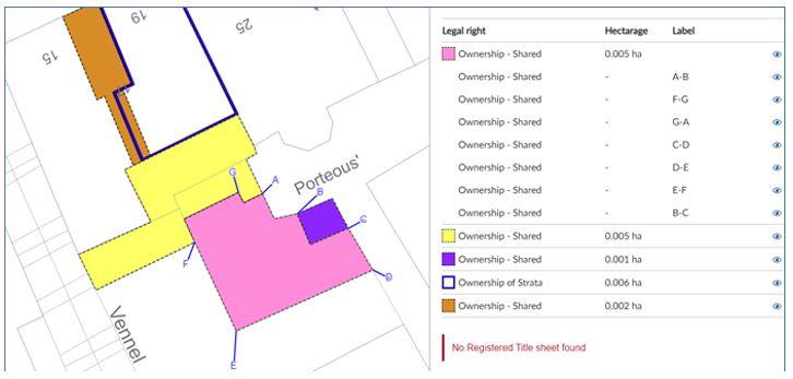
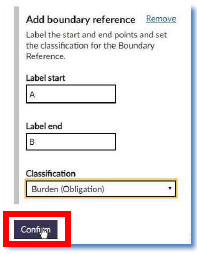
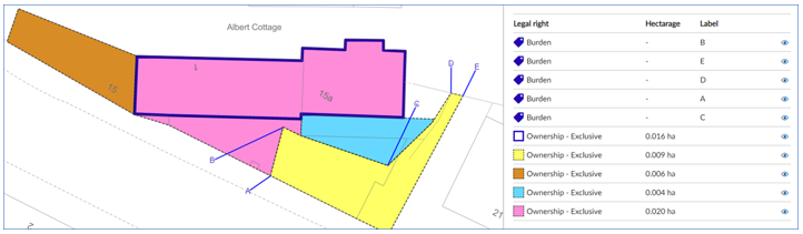
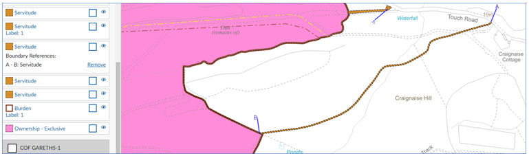
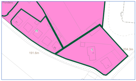
In the two images, below, the labels have been correctly added using the Add Boundary Reference function in the classification menu. The classification table shows these labels are associated with the respective polygon, and that they have been classified accordingly. The letters have also been correctly moved/dragged to draw the label/call-out lines. (Remember to Save and Print PDF to check that the text is visible on the print.) The classification of the boundary should reflect what is in the deed. For example, Burden if related to a burden, or Ownership - Exclusive/Shared if related to ownership. |
|
| |
 | |
In the two images, below, the labels have been incorrectly added using the Draw Point function in the Plan Creator. This means there is no link between the labels and the polygon borders; instead, the information associated with the label is only linked to a point which is incorrect in this scenario. In addition, in the first example, the letters have not been moved/dragged to draw the label/call-out lines, making it harder to interpret the exact location of the references. |
|
|
1.2 References affecting linear servitude polygons
If the subjects being registered have, for example, several access roads leading to them, and those servitude rights of access were created in the same deeds, or perhaps were granted in exactly the same terms in different deeds, then they will not need to be uniquely identified on the cadastral map and can be tinted the same colour. However, if there are specific burdens or conditions affecting those servitude rights, such as a burden to maintain a gate at point A or burdened to maintain the fences between points A & B, these should be associated with the relevant polygon using the Add Boundary Reference function.
Remember to move/drag the letter away from the polygon to generate the label/call-out lines.
Description
For boundary labels assigned to linear polygons such as this, the text colour (and any call-out line) will always be blue irrespective of the tint or edge colour applied to the polygon.
The boundary labels that are assigned to linear servitude polygons should be narrated in the title sheet as, for example, "tinted brown between the points labelled A to B", or "tinted brown between the points labelled A to C".
1.3 - Special situation - City of Edinburgh Council cases
It is common for historical conveyances by City of Edinburgh District Council to specify the ownership of the boundaries of a property in great detail. These are unlike those boundary references in other deeds that refer to the property extending to the centre line of wall on the north boundary or inner face of fence on east boundary and which are no longer labelled on the cadastral map unless they are also specifically narrated for burdens (see guidance in Property Section - Boundary Notes and References for more detail of the Keeper's policy on including boundary information in title sheets). Instead, the City of Edinburgh DC deeds specify the ownership of the boundary feature and therefore have to be reflected on the cadastral map.
| Example deed text & plan | |
| 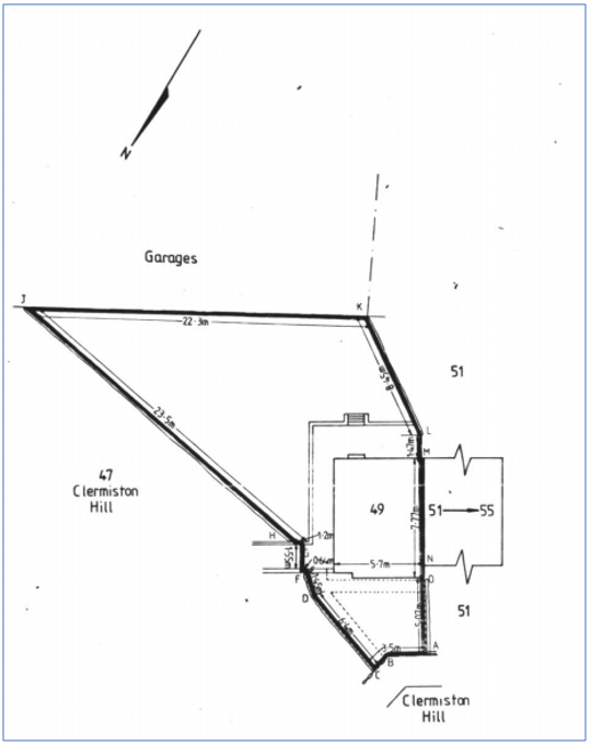 |
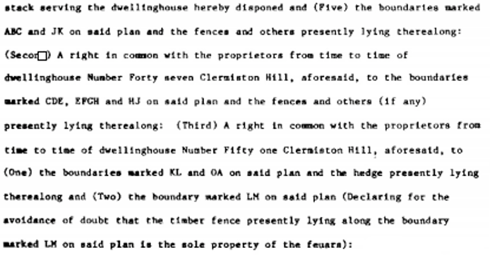
As you can see, there is a lot of detail contained relating to the ownership of the boundaries - some exclusively owned, others jointly owned. By examining all of the text relating to the boundaries, it may be possible to generalise or simplify some of these boundary references on the cadastral map. For example:
- for boundary ABC there is no division of this boundary in the deed as AB or BC so this could be simplified to AB on the cadastral map.
- Similarly, there is no specific need for all of the labels CDE, EFGH or HJ as that right in common is with one proprietor, and there is no division of these in the deed into smaller sections for burdens. So that whole boundary can be simplified to BC on the cadastral map.
The boundaries should be labelled using the Add a Boundary Reference function (see 1.0 above) so that the ownership references are associated directly with the relevant part of the polygon. They should be classified according to the description in the deed. Remember to move/drag the letter away from the polygon to generate the label/call-out lines.
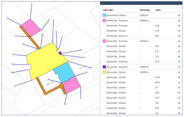
This is the cadastral map extract based on the example above after the boundaries have been considered & simplified. The classifications have been applied based on the text of the deed, and the call-out lines have been generated to create clear & visible labels. | 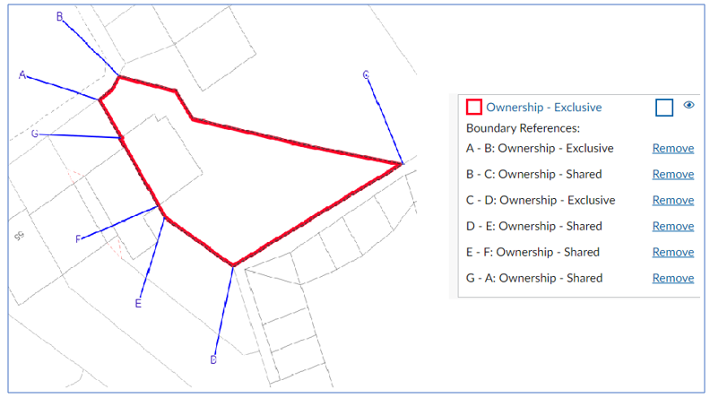 |
Each deed will vary in its description and will have to be considered individually, however the principle explained here can be applied to reduce the number of boundary references required leading to a simpler, less cluttered cadastral map.
As the boundary references in these deeds are so detailed and so complex, there are occasionally times where the same boundary point is required for two adjacent boundaries that have different levels of ownership.
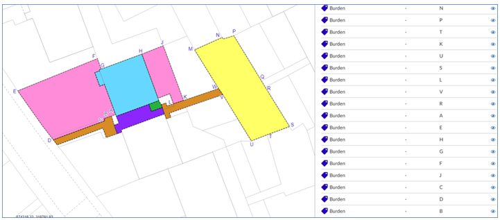
For example, in the image below:
- the boundary A-B is narrated in the deed as being exclusive ownership in relation to the pink tint, and
- the boundary N-A is narrated in the deed as being common ownership in relation to the brown tint.
If the two boundaries were referenced and classified as normal via the two polygons, this would mean point A was labelled twice (see image). This is not required for the title sheet or the cadastral map, and is therefore undesirable since it could lead to confusion.
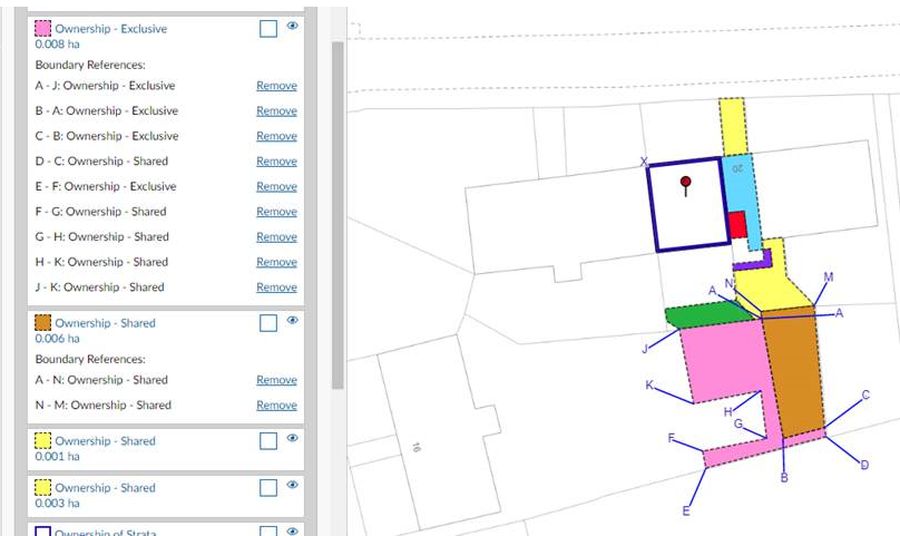
In a scenario such as this, you should only provide a reference in the Plan Creator for one of the boundaries. Those boundaries that are owned exclusively should take precedence over commonly owned boundaries. In this example, boundary A-B will be referenced, labelled and classified, whereas boundary N-A will not. the Points N & A are both already labelled in relation to other boundaries so will still be referred to in the text of the title sheet.
2 - Add a Label
2.1 Polygon labels
If the subjects being registered have, for example, several polygons of a similar nature that all need to be individually identified (for example, several route of title/burdens deeds, or several servitude rights of access that were created in different deeds and have were granted in different terms), then these can be tinted or edged the same colour but labelled uniquely to differentiate them. By using the Add Label function, the label is then linked with the polygon information.
Adopting this approach also has the benefit of creating consistency in the mapping by having, for example, all the servitude rights of access benefitting the subjects tinted the same colour. The same principle can be used for burdens affecting the subjects; for example, all the servitude rights of access burdening the subjects tinted the same colour. This is particularly useful in complex applications with many references as it aids interpretation of the title sheet.
Remember to move/drag the letter away from the polygon to generate the label/call-out lines.
Description
For labels assigned to edged polygons, the text colour will reflect the colour of the polygon edge, but the call-out line will always be blue.
For labels assigned to tinted polygons, the text colour will always be blue irrespective of the tint colour.
Labels associated with edged polygons in this way should be narrated as, for example, "the area edged and numbered 7 in brown". Labels associated with tinted polygons in this way should be narrated as, for example, "the area tinted yellow and labelled 3". (As all labels assigned to tinted polygons are blue, there is no need to add that info to the description).
Example
Each of the rights of access benefitting the subjects are tinted brown and labelled uniquely to allow them to be referred to individually in the title sheet. They would be described in the title sheet as, for example, "...tinted brown and labelled 1 on the cadastral map..." and "...tinted brown and labelled 2 on the cadastral map...
The various areas that require separate burdens references connected with routes of title have been edged and numbered in brown. They would be described in the title sheet as, for example, "...edged and numbered 12 in brown on the cadastral map..." and "...edged and numbered 7 in brown on the cadastral map..."
2.2 Lease, removal and feu polygon numbers
It is common practice on many titles to use edged and numbered polygons to reflect things such as areas that have been leased (yellow), areas that have been feued (blue) and areas that have been removed (green). Although mapping practice for new titles is moving away from using the green-out removal style to a positive removal style, and it is no longer appropriate to create a new title showing feus, you may find that you are dealing with an application that was previously created in the DMS and now needs to be updated on the Plan Creator. Leases continue to be shown on a landlord's title by yellow edges and numbers.
In all these scenarios, the polygon numbering should be applied using the Add Label function to ensure the number is associated with the polygon. The labels are added through the Classification menu in Plan Creator, and details of the process can be found in the Plan Creator Technical Guide - 5.0 Classifications.
When updating an older title, the DMS labels that were originally used should be deleted and the numbers re-applied to the polygons by Add Label.
Depending on what gives the clearest identification of the particular polygon being labelled, the number can be left within the polygon or dragged out of the polygon to generate label/call-out lines.
Description
For labels assigned to edged polygons, the text colour will reflect the colour of the polygon edge, but the call-out line will always be blue.
Labels associated with edged polygons in this way should be narrated as, for example, "the area edged and labelled 3 in yellow".
Example
The various areas that have previously been sold off from this historic parent title (mapped originally in the DMS) have been edged and numbered in green. They would be described in the title sheet as, for example, "...edged and numbered 1 in green on the cadastral map..." and "...edged and numbered 2 in green on the cadastral map...
2.3 Labelling to aid identification of very small polygons
Occasionally, it is necessary to label a very small polygon to make it easier to find or identify on the cadastral map. For example, a small bin store may not be clear on the cadastral map, even when viewed/printed at 1:1250. A label can therefore be added to the polygon to aid identification.
The polygon numbering should be applied using the Add Label function to ensure the number is associated with the polygon. The labels are added through the Classification menu in Plan Creator, and details of the process can be found in the Plan Creator Technical Guide - 5.0 Classifications.
Remember to move/drag the number away from the polygon to generate the label/call-out lines.
Description
For labels assigned to tinted polygons, the text colour (and any call-out line) will always be blue irrespective of the tint colour.
Labels associated with tinted polygons in this way should be narrated as, for example, "the bin store tinted mauve and labelled 1". As all labels of this nature are blue, there is no need to add that info to the description
Example
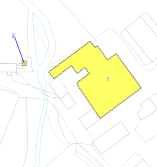
The gas governor site has been referenced with a number label, with the call-out line having been correctly created. It will be referred to in the title sheet as tinted yellow and labelled 2.
2.4 Labeling the ends of a polyline
If you are mapping a polyline that requires letter references for each end of the line, then the Add Labels tool should be used.
The letter references may be needed as they are specifically referred to in the burden (for example, the right to install a drainage pipe from point A to point B along the route coloured blue), or because there are several polylines of a similar nature that all need to be individually identified (for example, several servitude rights of drainage that were created in different deeds and have were granted in different terms), then these can be coloured with the same colour but labelled uniquely to differentiate them. By using the Add Label function, the label is then linked with the polyline information.
Adopting this approach also has the benefit of creating consistency in the mapping by having, for example, all the servitude rights of drainage benefitting the subjects shown with the same colour of polyline. The same principle can be used for burdens affecting the subjects. This is particularly useful in complex applications with many references as it aids interpretation of the title sheet.
The polyline labelling should be applied using the Add Label function to ensure the number is associated with the polyline. The labels are added through the Classification menu in Plan Creator, and details of the process can be found in the Plan Creator Technical Guide - 5.0 Classifications.
Check using the Save and Print PDF function that the letters are clearly visible. If they are not, then they should be moved/dragged to draw the label/call-out lines.
Description
For labels assigned to polylines, the text colour will reflect the colour of the polyline, but the call-out line will always be blue.
Labels associated with the ends of polylines should be narrated as, for example, "the water supply pipe shown with a blue broken line and labelled A to B in blue" or the "right of access shown with a broken brown line and labelled A to B in brown".
Example
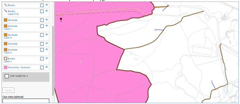
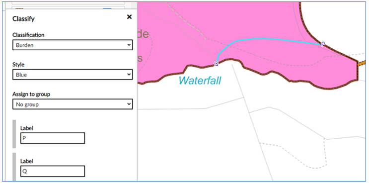
The water pipe referenced with a blue broken line is one of several such references shown on this large title. Each is labelled uniquely, with this particular one being "blue broken line and labelled P to Q in blue". To improve clarity, the letters P and Q should also be called out to create labels/call-out lines.
3 - Draw a Point
The Draw Point function should be used when labelled references are required to identify point features, for example septic tanks or wells. Details of the process can be found in the Plan Creator Technical Guide - 4.0 Toolbar (see 4.10).
It can also be used in unusual situations with particularly complex titles where it is not possible to associate a particular label with a polygon or polyline using either of the Add Boundary Reference or Add Label functions. If you are unsure if it is appropriate to use the Draw Point function with your title, please discuss with your referral point.
Precise point references - where the deed plan shows a precise reference for the point feature (perhaps a dot or cross on plan with a text label), the letter or number reference should be placed in the position of the point feature being labelled. Then move/drag the letter away from the point feature to generate the label/call-out lines thus creating a visible label on the cadastral map. The end of the call-out line now denotes the position of the point feature on the ground.
Imprecise point references - where the deed plan shows an imprecise reference for the point feature (no point or cross on the deed plan but just text indicating the approximate location of the point), the letter or number reference should be placed in the same position as the identifying text from the deed plan. Do not move/drag the letter away to generate label/call-out lines as this would result in a more precise representation of the point reference than was given in the deed.
Description
Labels added to the cadastral map using the Draw Point function will show the text in the colour that is selected in the classification box, but the call-out line will always be blue.
Labels associated with points in this way should be narrated as, for example, "the septic tank labelled ST in brown" or "the water tank labelled WT in blue".
Example
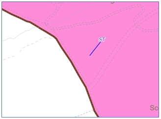
The septic tank has been referenced with a label - ST in blue, with the call-out line having been correctly created.
Registers of Scotland (RoS) seeks to ensure that the information published in the 2012 Act Registration Manual is up to date and accurate but it may be amended from time to time.
The Manual is an internal document intended for RoS staff only. The information in the Manual does not constitute legal or professional advice and RoS cannot accept any liability for actions arising from its use.
Using this website requires you to accept cookies. More information on cookies.
Feedback