4.0 Plan Creator Toolbar
- Editor9

There are various tools available to you to allow you to create your plan. The tools are located on the toolbar at the top of your Plan Creator window.
4.1 Copying and pasting polygons on the base and index layers

For every title you complete on the Plan Creator, you will need to copy at least one polygon from either the base layer or the index layer.
4.1.1 Copying from the base map layer
| a. Make sure the base map tab is selected. | 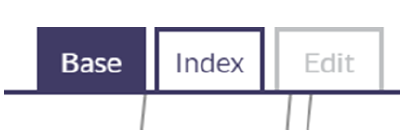 |
b. Click on the polygon you wish to copy - this will highlight it in blue. | 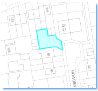 |
| c. Click on the copy/paste button on the tool bar. The selected polygon will automatically be transferred to the edit layer. | 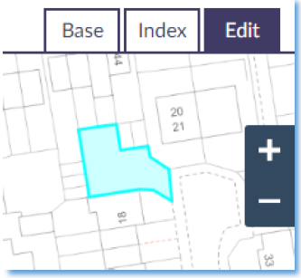 |
4.1.2 Copying multiple polygons
If your subjects are a house plot, for example, you will have to select the house and the garden that surrounds it.
To select multiple polygons, simply hold down the control key <ctrl> as you click on the required polygons.
Once you have all clicked on all the polygons you need, click on the copy/paste button.
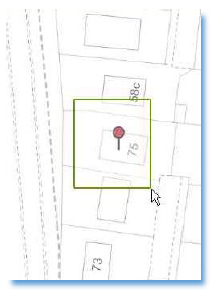
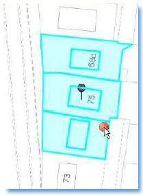
As an alternative to clicking on the polygons separately, you can also hold down the control key then click on the map. Whilst still holding down the left mouse button drag the mouse and draw a green box. When you release the mouse button all polygons that the green box intersected will be selected, and you can then click on the copy/paste button to bring all of these polygons forward to the edit layer.
If you have brought forward too many polygons, simply select the superfluous ones and press the <delete> key on your keyboard.
4.1.3 Copying from the index map layer
To select a polygon from the index layer, this is done in a similar way as copying from the base layer, the difference being that first you must complete an index search (see 3.2 The index layer). After completing the search, view the individual title or index that you wish to copy from and click to select the polygon(s) that you require - this could be all the references or only some of the references in that title or index.
Again, click the copy/paste button to bring them forward to the edit layer.
4.2 Duplicate Title

The Duplicate Title function allows a previously registered title to be duplicated into a new DCU/Draft Plan. This is particularly useful when a mapping style has previously been set up for common deeds using groupings. See guidance page Duplicating Titles in Plan Creator for useful information on how to make use of this functionality.
Selecting the duplicate title button displays the duplicate title option in the left-hand panel. Enter the Title number to be duplicated and select Continue. All mapped references in the registered title, including groupings, will be duplicated into the DCU/Draft Plan. | 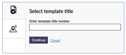 |
| Please note, if an attempt is made to duplicate a title that has not been approved the following warning message will appear; it is not possible to duplicate an un-approved title. | 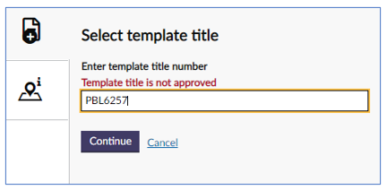 |
4.3 Undo and Redo map changes
| Undo map changes
|
| Redo map changes
|
Classifying a polygon does not constitute a map change |


4.4 Merge tool

The merge tool works in the opposite way to the split tool, in that it takes two (or more) selected polygons and merges them into one single polygon.
a. Select all the polygons that you would like to merge. Hold down the <ctrl> key while clicking to select multiple polygons at one time. |
| 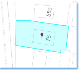 |
b. Click on the merge tool button (Hotkey CTRL + M can also be used). The selected polygons will be merged and replaced by a single polygon. | 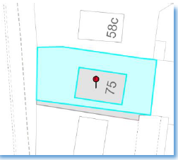 | |
When two or more polygons are merged, it is possible to retain the style & classification of one of the original polygons depending on the order in which they are selected.
For example:
- If you select a styled and classified polygon first, then an unstyled & unclassified autofill polygon second, when they are merged the style and classification of the first polygon will be retained for the new merged polygon.
- Or if a polygon classified as a burden is selected first followed by two polygons classified as ownership, when they are merged the new polygon will retain the classification of the first polygon - burden.
4.4.1 Fill or leave holes
When merging polygons, you may encounter this message
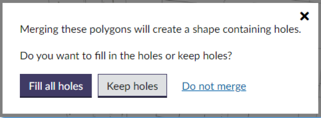
This is due to one of two scenarios with the polygons that have been selected:
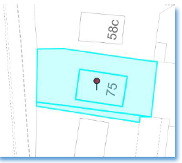
An island site can be intentionally created by not selecting the polygon(s) for the island. When the merge tool is used on the selected polygons, and the Fill all holes dialogue box appears, click on “Keep holes”. A single polygon with an island or hole will be created.
|

A shortcut can be used where you select all the perimeter polygons but don’t select the internal polygons. When the merge tool is used on the selected polygons, and the Fill all holes dialogue box appears, click on “Fill all holes”. A single complete polygon, including the originally omitted internal polygons, will be created.
Be careful when selecting “Fill all holes” that you are not filling an island site that you need to retain. |
4.5 Split tool

The split tool works by splitting a polygon into separate polygons. To do this, select the split tool, and the Plan Creator will display the grey vector points that can be used to split the polygon.
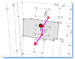
4.5.1 Splitting a polygon
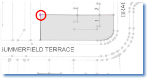
You can split a polygon by first clicking outside the polygon you want to split, then click on each point on the line you would like the polygon to be split along. The path of the split will be shown in pink, with each point that you clicked on shown by a red cross. Double click outside the polygon to complete the split.
The original polygon will now be split into separate polygons.
4.5.2 Reversing a split line
If the wrong point or points have been selected, you can undo the point selection one point at a time using the Undo map change button.
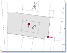
4.5.3 Deleting an unwanted polygon
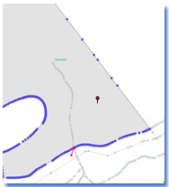
In most cases, the reason you are splitting a polygon is because part of that polygon is not required.
To delete the unwanted polygon:
a. Select the unwanted polygon by either clicking on the polygon, or |
|
| b. by selecting it in the left hand panel. | 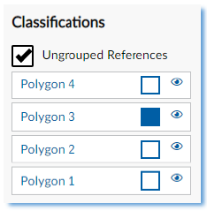 |
| c. Press the <delete> key on your keyboard. |  |
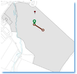
4.5.4 Using Ray Feature when splitting
When splitting a polygon, you may wish to make a split that is a ray from another feature. To do this:
a. Select the split tool. Click on the points of the line that you wish to ray from. |
|
| b. Press the R button on the keyboard (hotkey R) - this will bring up a ray and a perpendicular line. | 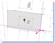 |
| c. Click on the ray or perpendicular line (it will snap to it) to correctly split your polygon. | 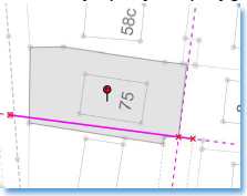 |
| d. The resulting polygons can then be deleted or categorised separately as required. | 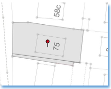 |
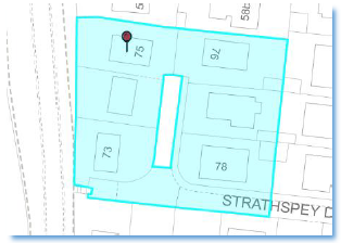
4.5.5 Creating an island site
There may be instances where an area within your overall extent is not to be included within your extent. You can use the split tool to define and split this area to then delete it.
(Please note, to remove areas that are wholly within a single polygon, see also 4.6 Cookie Cutter)
| a. Either create a framework of construction lines, or trace around existing features. |
|
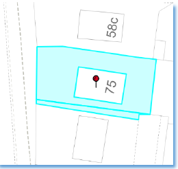
| b. Use the split tool to snap on the required points. | 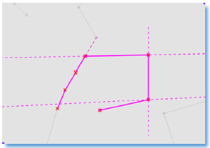 |
| c. Complete your split by snapping to the first point selected, or by crossing your split line at a desired point. | 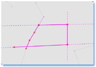 |
| d. A new polygon will then be created. | 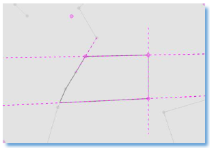 |
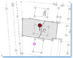
| e. Select the new polygon by either clicking on it or by selecting it in the left hand panel. | 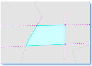 |
| f. Press the <delete> key on your keyboard to delete the new polygon and create an island site. | 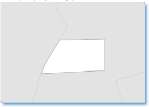 |
4.5.6 Trace
There will be instances where you may need to split along an OS feature where the points are too close together to allow the split. In these instances, you can use the trace functionality. The trace tool, when activated, will automatically include all points in-between two non-adjacent point on the same OS line.
The Trace tool is activated by pressing the T key on your keyboard when using the Split tool.
a. Click on the map canvas to start the split line then the first point on the line you wish to split along. |
|
| b. Press the T key on your keyboard to activate the Trace tool | 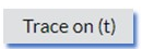 |
| c. Click on the last point you need along the required line. | 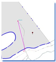 |
| d. All points along the line are now included. | 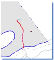 |
| e. Complete your Split as required. | 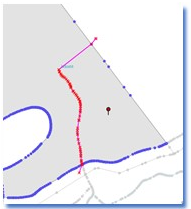 |
- If the wrong point is selected by accident, use hotkey Ctrl + Z to back up - this will maintain focus on the map canvas.
- If you wish to continue to trace another line/another section of the same line once you have selected a second point, simply press the T key on your keyboard to re-activate the Trace tool and select a further point.
4.6 Cookie Cutter

The Cookie Cutter is a tool for removing an area from within polygons, using existing polygons brought forward from the index layer or mapped in the edit layer that cannot be removed using the split tool.
| a. Create or bring forward the polygon that you wish to cut out of another polygon. |
|
| b. Make sure all polygons are hidden except from the primary polygon and the polygon you wish to remove from the primary polygon. | 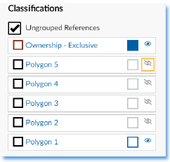 |
| c. Select the polygon to be removed (the cookie cutter tool will now be available) | 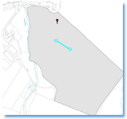 |
| d. Click on the cookie cutter button. |
|
| e. The area will now be removed from your primary polygon. | 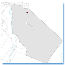 |
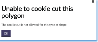
When the polygon you wish to use fully bisects the primary polygon, the cookie cutter cannot be used as it creates invalid geometry. The split tool should be used in such scenarios.

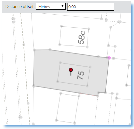
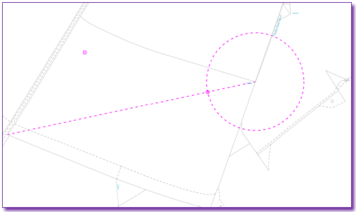
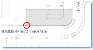
4.7 Distance Offset & Creating Guide Circles

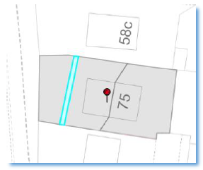
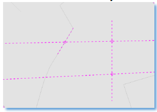
The distance offset tool is one of the construction tools within the plan creator. This tool helps you create shapes when there are no base or index polygons that can help. It works by drawing a guide circle at a chosen distance away from a point of your choice.. The tool draws a pink broken circle and drops pink construction points at this distance wherever it intersects either a polygon that has been brought forward to the edit layer or another construction element that you have drawn.
The tool can be used in three ways:
4.7.1 Freehand offset
| a. Click the distance offset button; like with the split tool, the grey vector points will now be displayed. |
|
| b. Select the required unit of measurement from the drop down menu. | 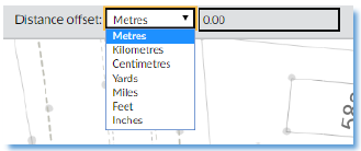 |
| c. Click on the point that will be centre of the circle (in other words, the point you wish to measure from). | 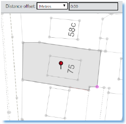 |
| d. Drag the mouse across the screen until the required distance is shown in the distance offset box and click the left mouse button to set the distance offset circle. | 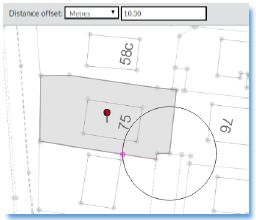 |
| e. Your distance offset circle is now displayed by a broken pink line, with pink construction points added at intersections. | 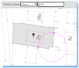 |
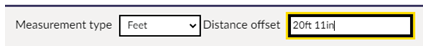
| Please note, when using feet as the unit, the distance offset is displayed as feet and inches. |
|
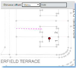
4.7.2 Pre-determined offset distance
| a. Click the distance offset button; like with the split tool, the grey vector points will now be displayed. | 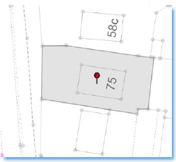 |
| b. Select the required unit of measurement from the drop down menu. | |
| c. Click on the point that will be centre of the circle (in other words, the point you wish to measure from). |
|
| d. Click in the measurement box. Enter the offset distance you require and press the <Enter> button on your keyboard. | 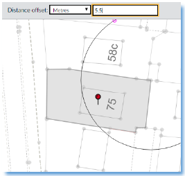 |
| e. Your distance offset circle is now displayed by a broken pink line, with pink construction points added at intersections. | 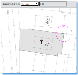 |
Please note, when using the distance offset tool and manually inputting a measurement in feet and inches, the entry can be typed as either “20 11” or “20ft 11in”. | 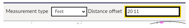
|

4.7.3 Creating a circular polygon or island site
This workaround method of creating a circular polygon or island site has been superseded by the Circle Tool (see section 4.12, below).
| a. Identify the centre point of the circle by triangulating from known features. |
|
| b. Use the Distance Offset tool to create a circle with the required radius. | 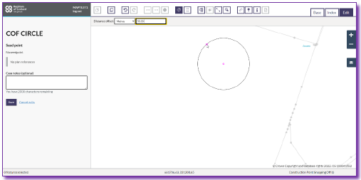 |
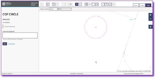 | |
c. Either: Bring forward the underlying polygon twice from the base map Or: Autofill the underlying area then copy and paste it. | 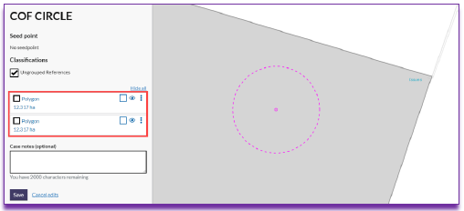 |
d. Select the distance offset circle you have already created. | 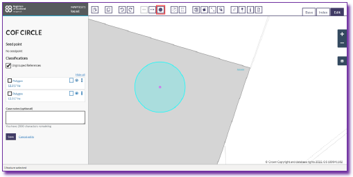 |
e. The Cookie Cutter tool will now be active. Click on the Cookie Cutter button and a hole will appear in the top polygon. |  |
| f. If you require the island site, you should delete the bottom polygon. | 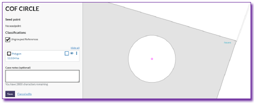 |
| g. If you require the circular polygon, you should delete the bottom polygon then use Autofill to create the circular polygon and then delete the outer polygon. | 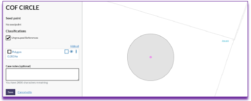 |
4.8 Parallel Line tool

The parallel line tool creates a parallel line from any two points you select on the map - this can be the blue vector points, the pink construction points, or anywhere you click on the map. This tool can also be used to create rays and perpendicular lines.
4.8.1 Parallel line
Freehand measurement of parallel line
| a. Select the parallel line tool from the tool bar. | |
b. Click on the two points you want to draw a parallel line from. |
|
| c. A pink broken line will appear. Drag this line until the measurement you require is displayed, and click again to display the parallel line. | 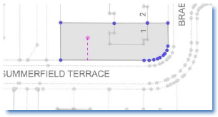 |
| d. To extend the parallel line, drag the mouse while you are measuring until the line is the desired length, or hit hotkey R on your keyboard to increase the extent of the parallel line. | 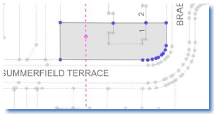 |
| e. Like the distance offset tool, the parallel line tool generates pink construction points wherever it crosses a polygon you have on the edit layer. | 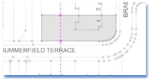 |
Pre-determined measurement of parallel line
Much like with the distance offset tool, if you know the distance the parallel line should be from the original feature, you can simply enter this into the "Distance offset" box and then press the <Enter> button on your keyboard. A parallel line will be placed at the required distance.
| Things to remember | |
|---|---|
1 The offset parallel line will be placed in the required place but will only be the length of the original line. |
|
2 If the hotkey R has been used, this will result in the extended parallel line being placed at the offset distance. | 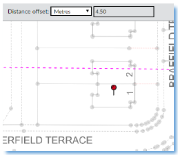 |
| 3 If the parallel line appears on the wrong side, then delete it and enter the offset distance as a negative value. | 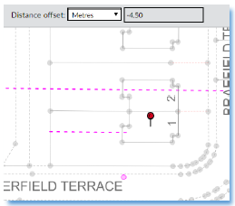 |
| Please note, when using the parallel line tool and manually inputting a measurement in feet and inches, the entry can be typed as either “20 11” or “20ft 11in”. |
|
4.8.2 Ray
| a. Select the parallel line tool from the tool bar. | |
| b. Click on the two points you want to do a ray from. | 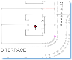 |
| c. A pink broken line will appear. | 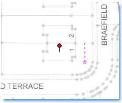 |
| d. Use the hotkey R on your keyboard to increase the extend the ray line. | 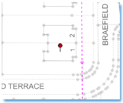 |
| e. Snap this ray line to one of the points your originally selected. | 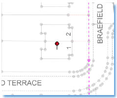 |
4.8.3 Perpendicular line
A perpendicular line can be created by using the hotkey P along with the parallel line tool.
| a. Create a parallel line as shown above (4.8.1) |
|
| b. Press the hotkey P to toggle between parallel and perpendicular line types. | 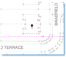 |
| c. Snap to the point you require the perpendicular line to be generated from. |  |
4.9 Auto-fill Tool

The auto-fill tool fills in a section of map that has not been previously copied through from the base layer.
The tool will only auto-fill until it reaches a base layer polygon, a polygon already on the edit layer, or a parallel/ray/perpendicular line.
First select the auto-fill tool, and clicking within the area you wish to fill and add as a polygon. As you can see, the auto-fill tool has added a polygon between the parallel lines and the polygons already brought forward from the base layer.
Once filled, you can use this new polygon as required (use as a separate polygon, merge it, or split it).
4.10 Shapeshift Tool

The shapeshift tool allows you to extend the extent of an existing polygon by tracing OS map detail.
A short demo video of how this tool can be used is available here - shapeshift demo.mp4 (ctrl & mouse click to open video in new window).
| The shapeshift tool is in the toolbar at the top of Plan Creator and is turned on by clicking the icon (highlighted in yellow below). To use this tool you must first select your polygon, only one polygon can be checked at a time. |
|
Once shapeshift is active you will see the vector points of your polygon shown in blue. Start reshaping the polygon by left clicking on one of these points. You can start tracing along OS map features. When tracing the OS detail if you require to turn the trace function off, to, for example, cross an area that is blank on the OS map, you can single left click. Once you reach your target OS point you can single left click and trace will turn back on. If you need to go back one or more points you can use the hot key ctrl z to undo then continue. |  |
| To complete your polygon you must double left click. |  |

4.11 Edge Match
![]()
The edge match tool enables polygons in registered titles, that were plotted onto prior versions of the Ordnance Survey (OS) map, to be snapped onto features on the latest version of OS Mastermap.
The edge match tool has been primarily developed for the processing of map updates (MUs) and is not intended to be needed for mapping the majority of new applications, where plans settle will be carried out on the latest version of the MasterMap in Plan Creator. However, the tool may be useful when mapping Complex DWs, updating parent title extents, and other secondary applications against registered titles.
Instructions for how to use the tool can be found at Edge Match Tool in the Plan Creator.
4.12 Circle Tool

The circle tool enables users to create circular polygons.
Once a circular polygons is created, it should be categorised and styled in the normal way. In addition, the circular polygons can be edited like other polygons, for example they can be split, merged, or amended with the shapeshift tool.
To create a circular polygon, select the circle tool by clicking on the icon in the toolbar. Then left click with your mouse on the centre point of the circle you wish to draw. The circular polygon can be drawn in two ways:
|
|
Once created, the circular polygon will appear as normal in the left hand panel list of features. It can then be selected, categorised, style added, and edited in the same way as any other polygon. |  |

4.13 Draw Line

Creates a line between two or more points.
| a. Click the draw line button. Click in the edit layer at the appropriate start point for the line. |
|
| b. Click at all the points of the line, adding as many additional points as required. | 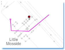 |
| c. Click the right mouse button on the last point created to finish the line. A line will be generated and added to the list of selectable items in the left hand panel. | 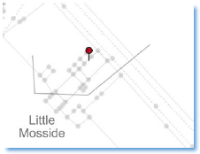 |

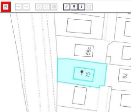
4.14 Draw Point

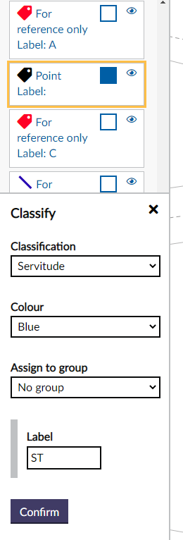
This is your labelling tool when you are required to identify a specific feature. Further guidance page Labelling using the Plan Creator provides additional information on the appropriate ways to label points, lines and polygons.
| Click on the draw point button, and then click the position of the point in the edit layer. | 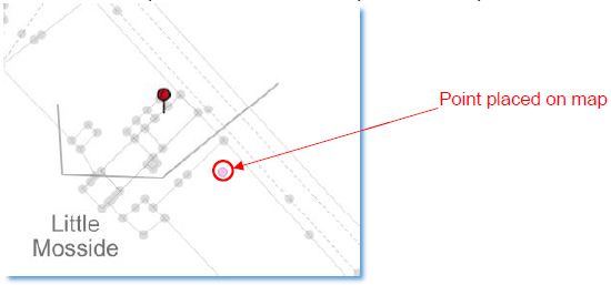 |
| The point feature should be classified appropriately, and labelled using the classification menu |
|
| The label text should then be selected and dragged away from the point to generate the call-out line. |  |
4.15 Measure Distance

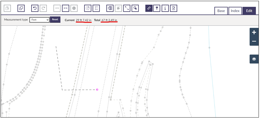
The measure distance tool measures the distance between any two points you would like to measure. Like the parallel and distance offset tools, you can change the measuring units by clicking on the drop down menu.
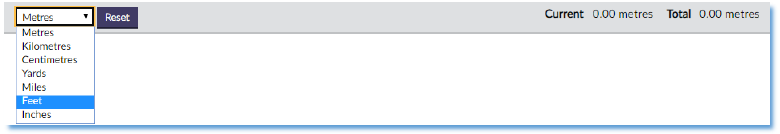
The toolbar displays two measurements - the current distance is the distance from the last point you have clicked, whereas the total distance is the sum total between each of the points you have measured.
To use the measure distance tool, select the tool from the toolbar and click on the first point you wish to measure from. As you can see, this line measures 11.83m. | 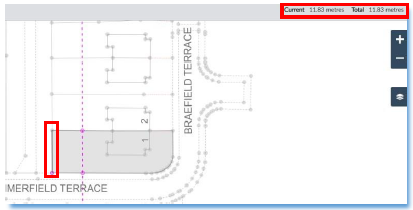 |
To continue measuring, click on the next point you wish to measure from and so on until you have completed measuring. When you have finished, click the right mouse button to finish. The line and the total measurement will remain on the map until you start a new measurement, deselect the measure distance tool, or select a different tool. | 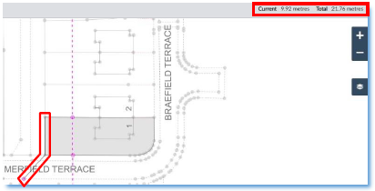 |
| When measuring distances on PC using feet as the unit, you will now see feet and inches instead of feet and decimals. |
|
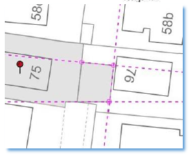
4.16 Add Seed Point

This tool allows you to manually place or move the seed point of your DCU file.
To do this, click the add seed point button on the toolbar, then click on the map where you want the seed point to be placed. It is important that the seed point is within the extent of your subjects. | 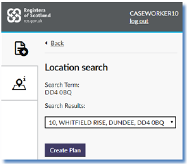 |
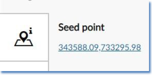
When you create the DCU file, the seed point will be automatically placed if you used an address or title number when searching for the subjects. If you only used a street name or town, etc when searching, the seed point will need to be placed manually before you can complete the COF or DCU file. Seed point information is shown on the left hand side of the screen. If the seed point is manually added or moved, no address will be shown; instead OS co-ordinates will take its place. |
|
4.17 Check Information

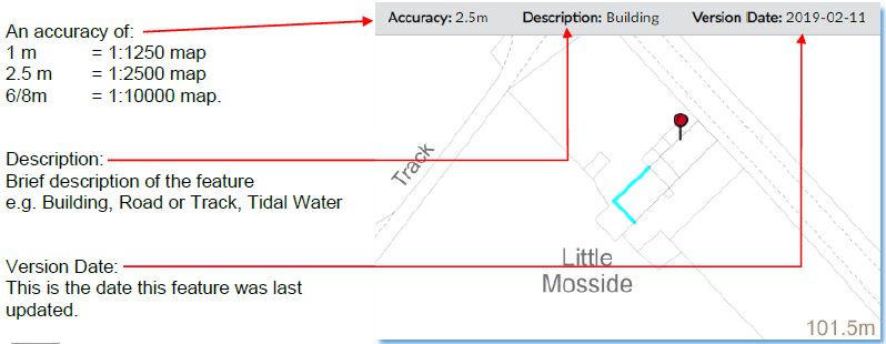
This tool allows you to check the OS data for any specific feature on the base map.
To use this tool, click on the check information button on the toolbar and then click on any base map feature or line. The line will turn blue to show it has been selected, and the relevant information will be displayed relating to the accuracy of the OS map for this feature, a description of the feature, and the survey date. It is importance to take note of the accuracy as this determines the tolerances you will work to.
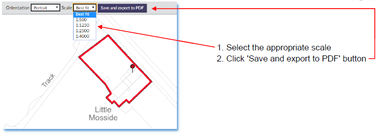
4.18 Save and Print

This function saves the DCU file to the database and prints/generates a copy as a PDF. Although this function was actually developed for use by the Reports team, it can also be used in registration as a print preview.
When using Google Chrome, the PDF that is generated will be sent to the Temp folder in the C: drive.
To use this function, a seed point must have been placed, each reference must have been classified, and all references must be visible.
| A pop up window will appear in the middle of the screen. Click the Close button. | 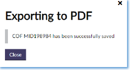 |
| At the bottom of the screen, a link will appear to the pdf. If you click on it, it will be displayed. |  |
Registers of Scotland (RoS) seeks to ensure that the information published in the 2012 Act Registration Manual is up to date and accurate but it may be amended from time to time.
The Manual is an internal document intended for RoS staff only. The information in the Manual does not constitute legal or professional advice and RoS cannot accept any liability for actions arising from its use.
Using this website requires you to accept cookies. More information on cookies.
Feedback