Basics of the Ordnance Survey Map
- Editor9
Basic principles of MasterMap Topography Layer
The basic principles as stated by the OS are
- OS MasterMap is a digital vector map and represents the real world as series of points, lines and polygons
- Each feature has associated geometry; this may be a single point for a symbol representing a mile post alongside a road, or two pairs of co-ordinates representing each end of a straight fence, or 17 pairs of co-ordinates representing an irregularly shaped building polygon.
- Each feature has associated attributes that give information about the feature such as its geometry, its real-world classification (road, building, fence, etc), and its unique identity.
- OS MasterMap is positioned on the British National Grid, allowing the use of National Grid co-ordinates to locate features.
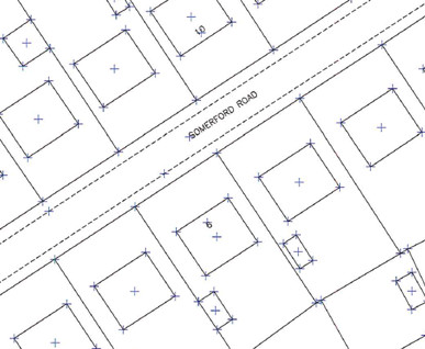
- OS MasterMap is captured at a base scale that is appropriate to the density of features in that area - 1:1250, 1:2500 & 1:10,000.
Vector mapping
The features in a vector map are made up of strings of X and Y co-ordinates, and are called vector points or map points. All the co-ordinates used in the MasterMap Topography Layer supplied to RoS are 2-dimensional and are based on the National Grid co-ordinate system i.e. easting and northings. The 3rd dimension, height, is not used by RoS at this time.
A feature on a vector map could be -
(1) A single point for a symbol representing something (for example, a mile post alongside a road, or a well). This single feature would have only one X and Y co-ordinate

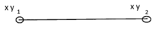
(2) Two sets of X and Y co-ordinates representing each end of a straight line feature (for example, a straight fence)
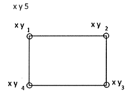
(3) A string of X and Y co-ordinates representing a polyline (a line made up of several straight line sections) or a polygon (for example, a right-angled fence or a rectangular house). In a string of co-ordinates where the feature to be depicted is a polygon the last XY co-ordinate is the same as the first. The software has to be given instructions on where to draw the last line
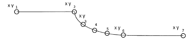
(4) Curved features are established by digitising intermediate points along the regular arcs which make up any curve. If these curved features are joined to a straight line section then they will become part of them and are not isolated. Such features can be part of polylines or polygons
Registers of Scotland (RoS) seeks to ensure that the information published in the 2012 Act Registration Manual is up to date and accurate but it may be amended from time to time.
The Manual is an internal document intended for RoS staff only. The information in the Manual does not constitute legal or professional advice and RoS cannot accept any liability for actions arising from its use.
Using this website requires you to accept cookies. More information on cookies.
Feedback