Mapping Styles and Plans References on the Cadastral Map
- Editor9
Styles used to define and describe the extent of a cadastral unit.
There are four basic methods that are used to define and describe the extent of the cadastral unit being registered:
- Red edging to reflect the precise extent of the cadastral unit.
- Tinting to reflect the precise extent of the cadastral unit.
- Red edging to reflect the extent of a tenement steading cadastral unit.
- Tinting to reflect the extent of a tenement steading cadastral unit.
If there is any doubt about the most suitable style to use to represent your cadastral unit, consult your referral officer.
1 Red edging to reflect the precise extent of the cadastral unit
This style is most suited to house plots or smaller areas of land, with no areas of shared or common ownership. Often additional tints or hatches within the red edge are required for specific burdens references.
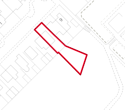
The conventional method for referencing a cadastral unit is to give it a red edge following the internal edge of the boundaries of the cadastral unit. This method of referencing can be used to reference, for example, a detached or terraced house, a plot of garden ground, a unit in an industrial estate, a smaller rural property, or a common drying green in a shared plot title sheet - it can therefore be seen that this method can and should be used in the majority of applications.
| Exceptions | |
| |
|  |
| |
|
2 Tinting to reflect the precise extent of the cadastral unit
This style is most suited to irregularly shaped plots of land that do not edge well, plots with island sites that do not form part of the cadastral unit, titles that also include areas of shared or common ownership, or for larger areas of land - tinting large titles facilitates a positive removal style for future Transfers of Part from the title.
There are several situations when referencing the precise extent of a cadastral unit with a red edge would not result in a clear entry in the cadastral map - in those situations, it is possible to reference the precise extent of the cadastral unit with tinted polygons.
Examples
- If the size or shape of the cadastral unit is so small or narrow that a red edge would look like a red fill when viewed or printed at the OS base map scale, then tinting method should be used.
- If a small or narrow tint reference close to the side of the cadastral unit would be obscured by a red edge, either tinting method or the use of a grouping should be considered.
- If the cadastral unit is large, for example a future housing development or a large rural estate or farm, tinting method should be used. This facilitates a positive removal style for future Transfers of Part from the title.
- If the cadastral unit is affected by island sites that do not form part of the cadastral unit, then tinting method should be used. The Cookie Cutter tool can be used to cut the island site out of the ownership polygon.
- If the cadastral unit is very complex, it may be more easily understood by the viewer if a tint is used rather than a red edge.
- If the property being registered includes common ownership of part of the property and the decision has been made to map the title under the transitional provisions in schedule 4 to the 2012 Act, tinting method should be used to provide separate plans references for the exclusive and common areas comprising the cadastral unit.
| For example, this is a shared plot cadastral unit for common areas in a development. Using a tint makes it easier to tell which areas are included in the cadastral unit than if red edges had been used. The island sites have been cut out of the ownership polygon in the Plan Creator. | 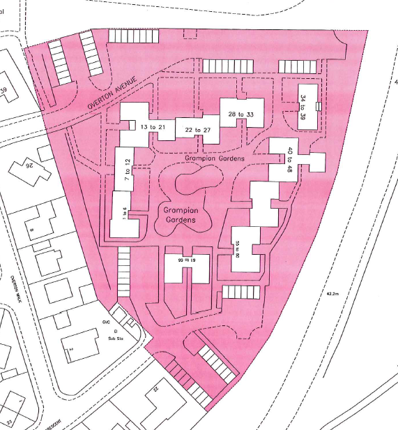 |
| For example, this cadastral unit is being mapped under the transitional provisions, comprising the house tinted pink, a 1/6th share in the drying area tinted blue & a half share in the coal shed tinted brown. | 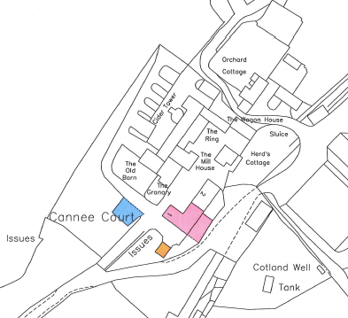 |
3 Red edging to reflect the extent of a tenement steading cadastral unit
- This style is most suited to non-development tenements. Often additional tint or hatch references within the red edge are also required to reflect precise extents for rights (including ownership of flat or pertinents) or burdens and these will be shown on groupings as supplementary data.
Section 16 of the 2012 Act allows the Keeper to create a single cadastral unit for a tenement steading. Each flat or unit within that tenement steading cadastral unit will have its own unique title sheet, and will be described in that title sheet as being a flat or unit that forms part of the tenement steading cadastral unit. See the Tenement Scenarios page for examples.
The conventional method for referencing a tenement steading cadastral unit is to give it a red edge following the internal edge of the boundaries of the cadastral unit. In the same way as with non-tenement cadastral units (see section 1, above), there are exceptions to when a red edge is appropriate:
| Exceptions | |
| |
| |
|
There will also be occasions when the Keeper is given sufficient information in an application to register a flat or unit within a tenement so that plans references can be provided for areas of common or exclusive ownership, rights or pertinents within the tenement steading. These plans references will not be shown on the primary layer of the cadastral map because the cadastral unit represents the whole tenement and not just one flat within it. Instead, a grouping will be created to show those references as supplementary data. Tinting method will normally be used to show the plans references in the grouping, although hatches and edges may also be appropriate depending on the complexity of the title.
4 Tinting to reflect the extent of a tenement steading cadastral unit.
- This style is most suited to tenements in developments where a deed of conditions describes rights and burdens that are common to more than the single tenement building, thus resulting in a larger, more complex tenement steading cadastral unit. Often additional tint or hatch references within the tenement steading are also required to reflect precise extents for rights (including ownership of flat or pertinents) or burdens and these will be shown on groupings as supplementary data.
Section 16 of the 2012 Act allows the Keeper to create a single cadastral unit for a tenement steading. Each flat or unit within that tenement steading cadastral unit will have its own unique title sheet, and will be described in that title sheet as being a flat or unit that forms part of the tenement steading cadastral unit. See the Tenement Scenarios page for examples.
There are several situations when referencing the precise extent of a cadastral unit with a red edge would not result in a clear entry in the cadastral map - in those situations, it is possible to reference the precise extent of the cadastral unit with tinted polygons.
Examples
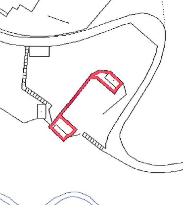
- If the size or shape of the tenement steading cadastral unit is so small or narrow that a red edge would look like a red fill when viewed or printed at the OS base map scale, then tinting method should be used.
- If a small or narrow tint reference close to the side of the tenement steading cadastral unit would be obscured by a red edge, either tinting method or the use of a grouping should be considered.
- If the tenement steading cadastral unit is affected by island sites that do not form part of the tenement, then tinting method should be used. The Cookie Cutter tool can be used to cut the island site out of the tenement steading polygon.
| For example, this is a tenement steading cadastral unit within a small development. There are some garages/parking spaces that do not form part of the tenement steading cadastral unit and therefore have to be treated as island sites. Using a tint makes it easier to tell which areas are included in the cadastral unit than if red edges had been used. The island sites have been cut out of the tenement steading cadastral unit polygon in the Plan Creator. |  |
There will also be occasions when the Keeper is given sufficient information in an application to register a flat or unit within a tenement so that plans references can be provided for areas of common or exclusive ownership, rights or pertinents within the tenement steading. These plans references will not be shown on the primary layer of the cadastral map because the cadastral unit represents the whole tenement and not just one flat within it. Instead, a grouping will be created to show those references as supplementary data. Tinting method will normally be used to show the plans references in the grouping, although hatches and edges may also be appropriate depending on the complexity of the title.
Hierarchy of plans references for polygons
Please note, in addition to the rules and guidelines set out below, there are also rules built into the Plan Creator for the render order of different types of plans reference - see Plan Creator Render Order Rules for details.
Over the years, a conventional order for the use of plans references in given circumstances has been developed and these principles should be observed to maintain consistency. The following are used in general practice: -
(a) Coloured Tinting
This is the most common method used for additional plans references and is used, where practical, in preference to coloured edging or hatching,
(b) Coloured Edging
This style is mostly used for additional plans references on large titles or historic Parent Titles but can also serve a useful alternative to tints,
(c) Labelling with numbers or letters
These are mostly used where the reference relates to a large area and should be combined with a coloured edging. The number or letter should be assigned as a label to the polygon. Numbers and letters combined with call-out lines (arrows) can also be used to reference very small areas or points. See Further Guidance page on Labelling in the Plan Creator for more details.
When adding letter references to areas, boundaries or points, it is best practice to avoid using letters I and O as these could be confused for the numbers 1 and 0.
(d) Coloured Hatching
Hatch references should only be used when all suitable tints, tints with associated labels, and edges have already been used for additional plans references. They should not be used for small areas such as parking spaces or garden ground, or for narrow linear features such as roads or tracks as these do not display well in pdfs or paper prints when viewed at basemap scale.
Edges - Double edging?
It is not possible to create double or stacked edges for references in the Plan Creator. Instead, appropriate use of other references or groupings should be used.
While the Edge Stacker Tool has been developed to allow for this style to be continued for historic titles when it is not possible to re-map them using groupings, etc., no new title should be mapped with double or stacked edges.
Edges to Reflect Removals on Parent Titles
Edging and numbering in green, known as greening-out, was historically used for referencing the extent of the cadastral units that have been removed from a larger cadastral unit (Parent Title), and whose whole interests have been transferred to other title sheets. When green edged polygons have been added to a historic Parent Title to reflect the extent of the removals, the double-edging will not be visible on the Parent Title in the Plan Viewer, but they will be visible on the PDF print generated due to the automatic application of the Edge Stacking tool.
In the Plan Viewer, the parent title red edge will be obscured if the removal green edge adjoins the parent title boundary. For simple or straightforward historic parent titles, consideration should be given to tinting the parent title extent, or re-mapping the removals positively (i.e. cutting them out). No new developments should be mapped using the green-out method.
In this historic Parent Title example, green edges (green-outs) were used to reflect the 3 house plots that had been sold out of the development. In the Plan Viewer, the result is double adjoining green edges and a partially obscured red edge. Although this will be clearer when a PDF print is generated due to the automatic application of the Edge Stacker tool, this style must not be used in new titles. Instead, the parent title extent must be reduced to omit the sold off plots. | 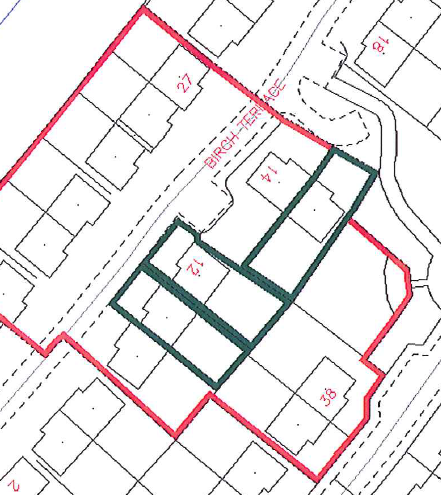 |
Edging a Tinted Polygon
Occasionally, you may have a polygon that needs to be tinted and edged (or hatched and edged). For example, your cadastral unit comprises several discrete areas and you are using tinting method for extent, so the ownership polygons are tinted pink. You then need to edge and number in brown two of those pink tinted polygons for two separate burdens references. In situations such as these, when a tint and an edge, or a hatch and an edge, are required for the same area, these should be created as two separate stacked polygons. This allows additional references affecting the area to be shown correctly (i.e. layered above the tint but below the edge), and for the different classifications to be applied to each polygon. The render order rules within the Plan Creator should ensure that the polygons are layered in the correct order (tint under edge), however it is advisable to double check this by generating a PDF print to ensure all references are visible.
Double-Layering of Polygons
If a polygon exists for ownership but another polygon is required to show a burden or right that affects only part of it, you will need to create and double-layer two polygons. For example, an ownership polygon is mapped, and another reference is needed to show the burden of a servitude right of access running over part of the ownership polygon. The ownership polygon should not be restricted or cut to adjoin the extent of the servitude, instead it should be mapped and classified to the full ownership extent. A second polygon should be mapped and classified showing the extent of the burdening servitude, and this should sit either beneath an edged ownership polygon or on top of a tinted ownership polygon (see Changing the Render Order guidance for how to re-order tinted polygons). This double-layering is required so that the data we collect and maintain in the land register gives a true representation of the ownership of land in Scotland.
| Edged ownership example | |
|---|---|
 | 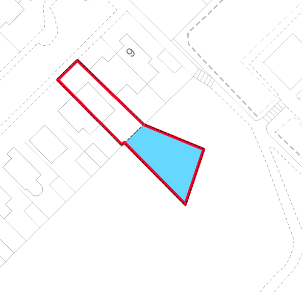 |
| A red edged polygon was originally used to define the extent of the cadastral unit. | Further decisions mean that a separate burdens reference is required for the area of ground at the rear, so a new polygon is created and tinted blue. The extent of the original red edged polygon should be retained, and classified as ownership, with the blue tinted polygon (classified as burden) sitting beneath the red edged polygon. The property description in the title sheet will read "Subjects.....edged red on the cadastral map" |
| Tinted ownership example | |
|---|---|
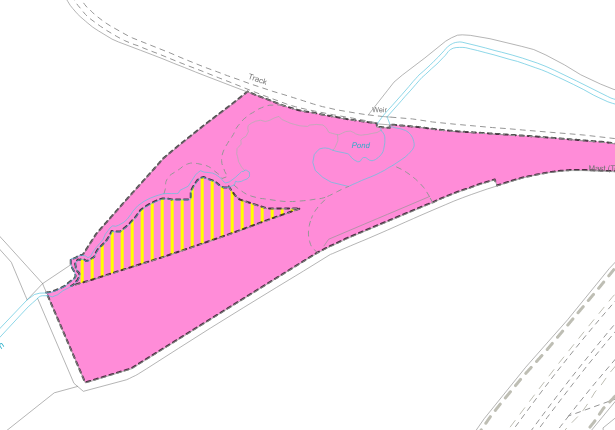
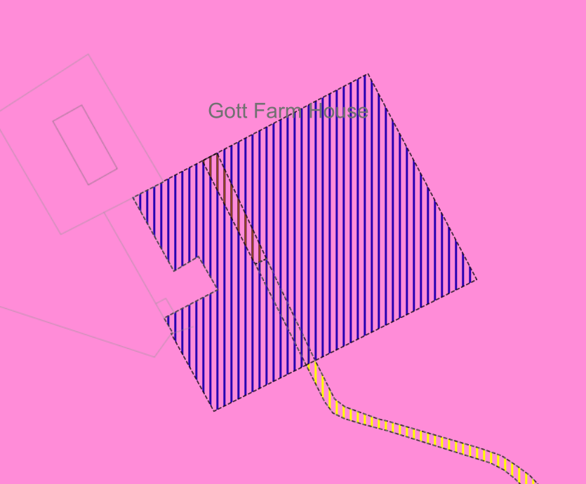
A pink tinted polygon was originally used to define the extent of the cadastral unit. Further decisions mean that a separate burdens reference is required for a smaller area within the cadastral unit, so a new polygon is created and hatched yellow. The extent of the original pink tinted polygon should be retained, and classified as ownership, with the yellow hatched polygon (classified as burden) sitting on top of the pink polygon. The property description in the title sheet will read "Subjects.....tinted pink on the cadastral map" |
|
Alternatively, depending on the colour references and styles already being used within a title, you may need to use a tint for a burdens reference. A new polygon is created and tinted blue. The extent of the original pink tinted polygon must be retained, and classified as ownership, with the blue tinted polygon (classified as burden) sitting on top of the pink polygon. The property description in the title sheet will read "Subjects.....tinted pink and blue on the cadastral map" However, if your title is particularly complex, please consider using the Groupings function to create an additional view or layer of the cadastral map to help with clarity of title references. | 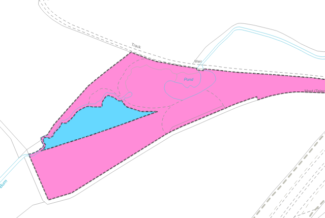 |
Double-layering of Hatches?
Although a hatched polygon can be shown on top of a tinted polygon, hatches should not overlap with other hatches.
The background to a hatch is transparent allowing an underlying tint colour to show through. However, the lines comprising the hatch pattern in one polygon will always sit on top of the lines comprising the hatch pattern in a lower polygon, meaning that only the top hatch will be seen by our customers when viewed in a pdf file showing their cadastral unit. Therefore, double-layering of hatches should not be used.
In this example, there are hatched polygons shown on top of a tinted polygon. In principle this is fine, except that the hatches also sit on top of other hatches making the extent of the various references unclear. When viewed in the pdf or as a paper print:
If your title is particularly complex, please consider using the Groupings function to create an additional view or layer of the cadastral map to help with clarity of title references. Please also avoid using hatch references for narrow linear features as these do not display well in pdfs or paper prints when viewed at basemap scale. |
|
How to Avoid Creating Unwanted Multiple Polygons
When copying and pasting polygons from previous titles on the Index Layer, it is relatively easy to accidentally copy through multiple versions of the same polygon if the user inadvertently clicks on the Paste button more than once.
As these duplicate polygons will all sit neatly on top of each other, it is not immediately obvious to the naked eye that duplicates exist. This will become apparent however when the user begins to classify the polygons in their title as it will be seen that there is more than one polygon listed in the draft plan for the same area. Any unwanted duplicates should be deleted.
Registers of Scotland (RoS) seeks to ensure that the information published in the 2012 Act Registration Manual is up to date and accurate but it may be amended from time to time.
The Manual is an internal document intended for RoS staff only. The information in the Manual does not constitute legal or professional advice and RoS cannot accept any liability for actions arising from its use.
Using this website requires you to accept cookies. More information on cookies.
Feedback